Detailed Engineering Steel Shop Drawings
Detailed Engineering Steel fabrication shop drawings are detailed drawings created specifically for fabrication and construction purposes. These drawings provide precise instructions and specifications to fabricators and contractors involved in the manufacturing and assembly of engineering structures or components.
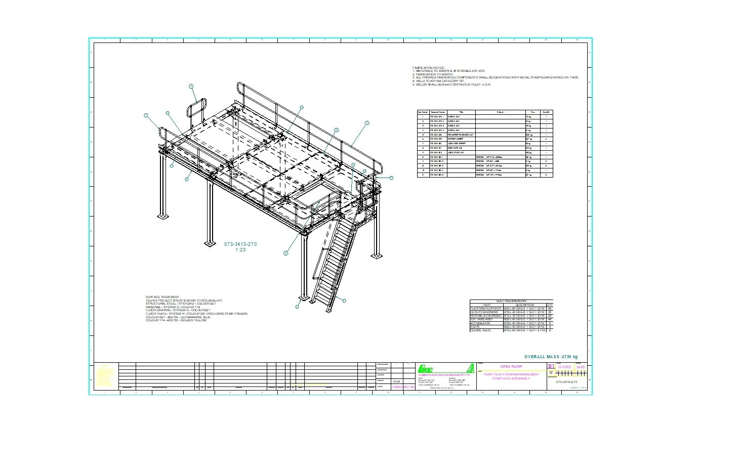
Fabrication shop drawings provide precise geometric information about the components or structures to be fabricated. They include detailed dimensions, tolerances, angles, and other measurements necessary for accurate fabrication.
The drawings specify the materials to be used in the fabrication process, including type, grade, dimensions, and any special requirements. This ensures that the correct materials are used to achieve the desired performance and quality.
Fabrication shop drawings illustrate how the components or structures are to be assembled. They provide step-by-step instructions, including welding details, fastening methods, and assembly sequences. This helps fabricators understand the correct order and techniques for assembly.
For welded structures, the drawings provide specific details about weld types, sizes, locations, and welding symbols. This ensures that proper welding techniques and standards are followed during fabrication.
Fabrication steel drawings often include a bill of materials (BOM) that lists all the required components and quantities necessary for fabrication. The BOM helps fabricators accurately procure the necessary materials and manage inventory.
Fabrication shop drawings play a crucial role in communicating design intent, facilitating accurate fabrication, and ensuring the desired quality and performance of engineered components or structures. They serve as a bridge between the engineering design and the fabrication process, providing clear instructions and specifications to fabricators to bring the design to life.